Sintered Metal Filter Systems for Process Industries

Key takeaways:
- Sintered metal filters are highlighted for their high particle removal efficiency, durability, and ability to withstand harsh conditions like high temperatures and corrosive environments.
- They are designed for continuous service in industries such as oil refining, chemical and petrochemical processing, and pharmaceutical manufacturing.
- The filters support various cleaning methods, including backwashing, to ensure long service life and consistent performance.
- Sintered metal filter media are customizable in terms of alloy material and pore size to meet specific application requirements, enhancing filtration efficiency and operational reliability.
Filtration systems, utilizing sintered metal media for solids/liquid separation, have proven to be an effective and economical alternative to other separation methodologies, which may be vulnerable to pressure spikes, high temperatures, and / or corrosive environments.
These harsh environments, often demanding use of continuous service, are ideally suited for all-metal filtration system utilizing sintered metal media, which have been fabricated into tubular metal elements. Sintered metal media have demonstrated high particle efficiency removal, reliable filtration performance, effective backwash capability, and long on-stream service life in many industrial applications that typically utilize leaf filters, bag filters, and plate and frame filters.
Sintered metal media provide a positive barrier to downstream processes. Sintered metal can also be used to support finer filter membranes, precoated, or used as filter septum when they are coated with ion exchange resins. In addition to providing superior filtration in a single pass, clean-in-place backwashing reduces operator exposure to process materials and volatile emissions. While applications include sustained high temperature and corrosive environments, any pressure driven filtration process with high operating costs has the potential for improvement using sintered metal filtration technology. Suitable applications are found in oil refineries, chemical and petrochemical processes, and pharmaceutical production facilities.
Principle Features and Properties of Sintered Metal Filters
The development of specially designed and engineered sintered porous metal media, with a stable porous matrix, precise bubble point specifications, close thickness tolerances, and uniformity of permeability assures reliable filtration performance, effective backwash cleaning and long on-stream service life. These well-controlled pores are essential to ensure effective particulate removal from process streams, coupled with subsequent particle removal during a backwash process. The particulate matter may be an undesirable contaminate, the desired product of the chemical process, or a reusable catalyst. Removal of the particulate matter may improve the quality (value) of the downstream liquid stream or aid in the subsequent processing of a wastestream.
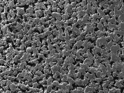
The permanent structure of sintered metal media allows filter cartridges to be cleaned in several ways with no media migration. A SEM photomicrograph of sintered metal media is shown in Figure 1.
Figure 1: SEM Image of sintered porous metal grade 2 media.
The appropriate selection of alloy type for corrosion resistance, and media grade for particle removal, assures liquid purity during separation. In-situ cleaning in process filters is by liquid or gas backwash. Chemical cleaning with compatible materials or ultrasonic cleaning in a detergent solution will remove insoluble contaminants from the filter. Sintered metal media are available in a wide variety of corrosion resistant alloys including: Stainless Steel 316 L, 304L, 310, 347, and 430; Hastelloy® B, B-2, C-22, C276, N and X; Inconel® 600, 625, and 690; Monel® 400; Nickel 200; Alloy 20; Titanium.
Sintered metal media are offered in grades 0.1, 0.2, 0.5, 1, 2, 5, 10, 20, 40 and 100. Sintered porous metal offers a temperature range of 750 to 1750°F depending on alloy material and atmospheric conditions. Table 1 shows elevated service temperatures of several sintered metal alloys.
Table 1. Elevated temperature service for selected sintered metal alloys.
|
Maximum Temperature |
||||
| Material | Oxidizing Atmosphere | Reducing Atmosphere | ||
|
°C |
°F |
°C |
°F |
|
|
316L SS |
400 |
750 |
482 |
900 |
|
Iconel 600 |
593 |
1100 |
815 |
1500 |
|
Hastelloy X |
788 |
1450 |
927 |
1700 |
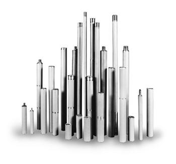
Sintered metal filter elements can be supplied to withstand differential pressures over 3000 psi. Sintered metal is permanent media with an all welded construction. The media can withstand pressure spikes with no media migration. An assortment of fabricated sintered metal cartridges is shown in Figure 2.
Figure 2. Sintered porous metal cartridges are available in a variety of shapes, media grades, and alloys.
Filtration properties are dependent on the media characteristics, the surface area available, and the process conditions of the application. Particle retention, media uniformity, absence of particle shedding, and cleanability are critical to the filter operating system. Laboratory feasibility assessment provides a suitable basis for determining filter design specifications. Pilot scale testing ensures the filter meets operational specifications under process conditions.
Filtration Principle
Sintered metal filters are high efficiency, two-dimensional, straining type with particulate being collected on the media surface. The proper selection of media grade must balance the needs of the filtration application regarding particle retention, pressure drop and backwash ability. There are basically three process factors to consider: fluid velocity through the filter media, fluid viscosity and particle characteristics. The important particle characteristics are particle shape, size and density. Particles that are hard, regular shaped and form incompressible cakes such as FCC catalyst are well suited for surface filtration.
Filtration operation is based on constant flow, increasing pressure drop until the terminal pressure drop is reached. Terminal conditions will be reached when the catalyst cake thickness increases to a point where the fluid flow pressure drop is at a maximum for a given flow and viscosity condition. The filter is then backwashed by pressurizing the filter with gas, then quickly opening the backwash discharge valve. This backwash procedure generates a momentary high reverse differential pressure, which effectively removes solids from the media surface. Reverse flows of clean liquid (filtrate) through the media assists in the removal of solids and flushes them out of the filter.
The uniformity in the pressure drop over time for repeated cycles in filtration operations using sintered metal media is shown in Figure 3.
Figure 3. Pressure profile for multiple cycles using Mott grade 0.5 media
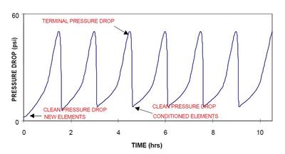
Uniformity in the rate of rise of the pressure drop indicates the feed slurry particle size distribution remains constant, as does the slurry concentration. The inside-out filter configuration, utilizing filtration media with uniform porosity, builds a uniform cake on the inside surface of the filter element that improves particulate removal and backwash efficiency. Recovery pressure after backwash increases slightly once media is conditioned, but should be within 2-3 PSI of the clean flow pressure drop. Filter media recovery pressure drop must be stable for consistent performance. Proper backwash methods and procedures must be followed for good media cleaning. Changes in the fluid temperature will affect viscosity and, thus, the rate of rise pressure drop across the media; therefore, design-operating temperatures should be maintained throughout filtration process.
Filter System Description and Operation
There are two methods of operating an inside-out filter: 1) Static or barrier type filtration and 2) Dynamic or crossflow filtration. The variations exist primarily in the method of backwash or blowdown, and secondarily in the method of feeding and concentrating. In the static/barrier method, solids are deposited on the wall of the tube and fluid passes through the wall as filtrate. Fluid flow is generally perpendicular to the element wall. The dynamic or crossflow method incorporates a fluid flow of circulating solution axially through the element of sufficient velocity to prevent significant solids accumulation. The resulting effect is to concentrate a dilute feed stream to high solids content and reduce pressure drop due to flow through the solids cake.
Filtration using sintered metal media uses three primary types of filter configurations for solid/liquid filtration: 1) Outside-in filtration: traditional solid/liquid barrier separation occurs on the outer perimeter of a closed-end tubular filter element. 2) Inside-out filtration: solid/liquid barrier separation occurs on the inside of a closed-end tubular filter element. 3) Inside-out (multimode) filtration: solid/liquid (barrier or crossflow) separation that occurs on the inside of open-ended tubular filter element. Filtration is with multi-option top or bottom feed inlet.
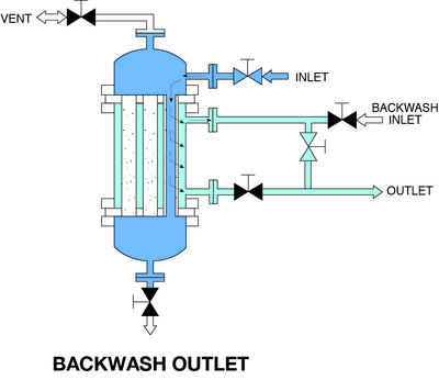
Inside-out filters, as illustrated in Figure 4, were developed by Mott Corporation in 1984 for a myriad of industrial applications including catalyst recovery.
Figure 4. Inside-out barrier filter configuration

Inside-out filtration is ideal for applications with solids with low settling velocity to ensure that solids will be carried into the element. A more stable cake forms on the inside of the element and each element operates independently. Elements can be close to each other resulting in smaller housings and less liquid holdup volume. Solids can be washed and backwashed via slurry backwash, empty shell gas backwash, or wet cake discharge. Attributes of inside-out filters include:
- Configuration is more efficient than outside-in filtration as there is less heel, minimal loss of filtrate, and easier discharge of solids.
- Elements can be selected based on solids holding capacity, therefore optimizing packing density.
- Using the upper filtrate outlet assures filter cake deposition through the full length of the element.
- Using the lower filtrate outlet allows displacing of the filtered liquid from the shell with gas,
- increasing product yield and producing a higher concentration slurry backwash.
The inside-out multimode filter, illustrated in Figure 5, is similar to the inside-out filter, but the element is open on both ends, and is sealed within two tube sheets.
Figure 5. Inside-out multimode configuration
The inside-out multimode filter can be operated as a light solid polishing filter where liquid clarification is the objective, to a high solids recovery filter of catalyst or product solids. The multimode crossflow configuration can be operated continuously, with a side stream removal of the concentrate, or as a batch process with the recirculation terminated after desired concentration is reached. Once the batch is filtered, the barrier mode can be used to evacuate the solids either as a slurry backwash or wet cake discharge. Dewatering cake with air, steam or other gas will concentrate solids to 40-50%. Backwash is similar to inside-out backwash modes. Bump-and-settle allows concentration of solids without draining the filter element or housing, therefore optimizing product yield. A continuous loop reactor system may not require backwashing. Advantages of inside-out multimode filters include:
- Top-feed configuration is most advantageous with high specific gravity solids that have a high settling rate. Classification of the solids can occur in an upflow mode.
- Filter provides high efficiency solids removal, stable cake and excellent cake washing capabilities.
- System can be operated in both the barrier or crossflow mode.
- Single vessel filters are recommended where flow rates allow and flow can be stopped for a few minutes for the backwash, or if off line periods can be tolerated for maintenance.
- Two filter dual systems are recommended where continuous flow is required and short periods of off line can be tolerated for maintenance.
- Three filter systems are recommended for continuous operation, even during maintenance periods.
Feasibility Testing
Filtration properties are dependent on the filter media characteristics, the surface area available, and the process conditions of the application. Laboratory feasibility assessment provides a suitable basis in determining filter design specifications. Pilot scale testing ensures the filter meets operational specifications under process conditions. Testing can provide the following information: verification of solids particle size, shape, concentration and filtering characteristics. The only valid way to evaluate sizing and performance is through testing. Information obtained from feasibility and pilot scale testing includes:
- Obtain sizing data for scale-up and verify operation conditions.
- Introduce and train operating personnel in filter operation.
- Challenge the filter with variations in the process conditions.
- Obtain long term operating information for cleaning and maintenance scheduling.
- Evaluate the effect of extended operation on different media.
- Materials compatibility testing.
Pilot Filter Case Study: Backwash Filter Performance Slurry Oil Filtration
Pilot studies at a commercial refinery used a 10 GPM (340 BPD) automated pilot filter to verify filter operating performance and media selection in tests conducted during a two-month trial. The filter was cycled continuously between filtration and backwash, with more than 2500 cycles performed. Backwash liquid was intermediate cycle gas oil. Tests were conducted to maximize the number of cycles during the test period. Filter performance with various media grades is summarized in Table 2.
Table 2. Pilot filtration testing using Mott grades 0.5, 2 and 5 media.
|
Feed Conc., TSS, ppm |
Particle Size Range, μm |
Avg. Particle Size, μm |
Media Grade |
Filtrate, TSS, ppm |
Operating Flux, gpm/ft2 |
|
1000 |
N/A |
< 10 |
0.5 |
< 20 |
N/A |
|
750-1000 |
N/A |
10-12 |
2 |
10 |
0.25 |
|
500-1000 |
1-30 |
20 |
2 |
10-15 |
0.1-0.5 |
|
1200 |
1-190 |
30 |
5 |
91 |
0.5 |
|
1500 |
1-190 |
30 |
0.5 |
10 |
0.34 |
Figure 6 shows a uniform pressure profile comparing the rate of rise in pressure drop over time of grade 2 media after 1, 4 and 30 days.
Figure 6. Pressure profile comparison
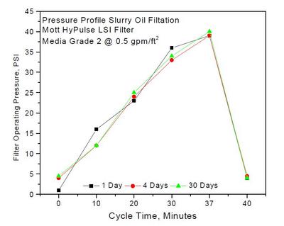
Slurry oil concentration ranged from 500-1000 PPM. Average particle size was about 20 μm. The filtration cycle was about 40 minutes with terminal pressures of 37 – 40 PSI. Recovery pressure after backwash ranged from 2-5 PSI. Filtrate quality was less than 25 PPM TSS with most cycles < 10 ppm or less. Increase in solids concentration will shorten cycle time as pressure drop increases at a faster rate.
This effect can be overcome somewhat by increasing the cycle terminal pressure drop. If the increased solids concentration is due to the addition of large particles increased solids cake permeability may result, which will increase the solids loading capacity at the same pressure drop.
Applications
Sintered metal media have been used in a myriad of separation applications over the past 40 years, with a few examples in the following application cases. The first three cases used a triple filter system capable of continuous filtration. Case 4 uses the filter housing in a recirculating loop around the reactor.
Case 1
This filtration process required a rugged backwashable filter to captured abrasive fines > 2 μm and reduced chemical oxygen demand (COD) in a crystallizer tails polishing application. Solids were returned back to a crystal separator for zero waste production and minimal wastewater contamination. Porous backwashable media proved to be economical, as the filter cartridges operated with multiple daily backwashing for over 6 years.
Case 2
Sintered metal filtration technology offers an alternative to centrifuges for spent catalyst recovery applications. Filtration provided filtrate quality of <1 ppm suspended solids and backwashes concentrated solids that were sent off site for recovery. This filter system operated successfully for over 7 years, with spent catalyst recovery savings paying for the filtration system a little over 1 year.
Case 3
FCC slurry oil filtration systems have been installed at major refineries in China with capacities from 100 mt/day to over 350 mt/day. Since 1997, porous metal media is applied to more than eight FCC slurry oil filtration systems in China and majority of the systems were installed with existing RFCC units. The typical RFCC slurry oil unit operates at about 350°C and 20 kg/cm2, with a catalyst solids concentration from 2000 ppm to as high as 12,000 ppm. Filtrate quality is less than 50 ppm representing a 99.5% or better efficiency. The clean FCC slurry oil is used as clean fuel, feedstock for manufacturing various high grade petroleum coke, carbon black. The clean FCC slurry oil is used as clean fuel, feedstock for manufacturing various high grade petroleum coke, carbon black. The clean FCC slurry oil can also be used, after going through the aromatics solvent extraction unit, as a good feedstock to various hydrocarbon processes including RFCC itself. Refinery applications use inside out dual or triple filter systems for removal of FCC catalyst fines from slurry oil. Figure 7 shows a schematic diagram of a dual filter system.
Figure 7. Schematic of automated dual filter system
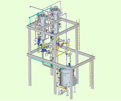
These totally automated systems are designed to handle high flow rates in continuous operations. Extended cycle time were obtained by running two filters simultaneously, but staggered in cycle time, with the third filter on standby for use when one of the online filters requires backwashing. Removal of catalyst fines and other particulate not only improve the oil product, but it protects downstream equipment from fouling, and reduces equipment maintenance.
Case 4
Filtration used a multimode filter in an isomerization reaction to recover fine, suspended catalyst (0.5 – 100 μm) from a continuous flow stirred tank reactor (CSTR). This technology replaces multiple candle type filters, requiring sock replacement as well as secondary cartridge filters to maintain constant product flow. Advantages of multimode filter, operating in a recirculating loop around the reactor; increased catalyst life by eliminating frequent shutdowns required using filter socks and cartridges. Catalyst recovery increased, as did product yield. The filter cake was controlled by recirculation rate while producing filtrate measuring < 0.01 ppm total suspended solids.
Case 5
Sintered metal media has been used in spent resin handling systems for polishing wastewater recovered from the resin blowdown and for radwaste volume reduction in the removal of resin, crud and iron oxides. Sintered metal media have demonstrated excellent stability characteristics, even under deliberate upset conditions, making it ideally suited for nuclear applications. Power generating plants require low resin leakage (0.1 parts per billon or less) to prevent corrosion in the steam generator or reactor. Resin leakage at full flow using sintered metal media is consistently below one tenth of a part per billion.
Case 6
Sintered metal filtration media is used in the downstream petrochemical and fine chemical industries. Filtration systems are installed in various PTA (Purified Teraphthalic Acid) processes to improve the production yield, improve the product quality, recover valuable catalysts and reduce the loading to the waste treatment unit.
Summary
Sintered metal media are bi-directional, and will perform equally well with either inside-out or outside in design. The media are re-useable due to its structural integrity, and chemical and thermal compatibility. Consequently, these media develop into a backflushable, cleanable filter that can employ filtrate, gas or some other process compatible fluid for backwash. Variations in the filter housing design will optimize filter performance efficiency. The benefits of inside-out filtration include stable cake formation resulting in consistent, high quality filtrate. Plug flow liquid displacement minimizes liquid consumption during cake washing, therefore minimizing the amount of wash liquid. Cake dewatering is possible with gas displacement of the liquid accumulated in the filter element, and on the clean side of the filter. Overall, this technology reduces solids contamination of liquid products and optimizes solids recovery.
Written by Dr. Kenneth L. Rubow & Louise L. Stange
Hastelloy is a registered trademark of Hayes International, Inc.
Inconel and Monel are registered trademarks of International Nickel Co., Inc.
FAQs: Sintered stainless steel filter
Q: What is a sintered stainless steel filter?
A: A sintered stainless steel filter is a type of filtration device made from stainless steel powder that’s been compacted and sintered to create a porous structure, offering high filtration efficiency.
Q: Why choose sintered stainless steel filters for industrial applications?
A: These filters are highly durable, resistant to corrosion and high temperatures, making them ideal for demanding industrial environments where reliability and longevity are critical.
Q: Can sintered stainless steel filters be cleaned and reused?
A: Yes, one of the key advantages of sintered stainless steel filters is their ability to be cleaned and reused multiple times, offering cost savings over disposable filters.
Q: How do you determine the right pore size for a sintered stainless steel filter?
A: The appropriate pore size depends on the specific application’s requirements, including the size of particles to be filtered and the desired flow rate, ensuring optimal filtration performance.